Camera
Introduction
Since its first release, Processing has been known for its capacity in creating visualizations. It’s strength in manipulating pixels of images enables more experimentation when external image sources, like cameras, are used.
While interesting and meaningful, using the built-in camera of the laptop or desktop computer with Processing can be limited by the form factor and the input methods of the computer. The portability and expandability of Raspberry Pi single-board computers opens up new frontiers for using camera as input for Processing sketches.
The combination of Processing, camera, and a couple of components connected to Pi’s GPIO pins could be used to make some unique experiences while remaining affordable. Think of possibilities like:
- Portable cameras with filters that are controlled by physical buttons and knobs
- Portrait booths that generate artwork based on recent snapshot
- Computer Vision experiments
- Timelapse rigs
- and more

Of course this is just a short glimpse of what’s possible. The knowledge you gain in this tutorial should enable you to create your own projects using camera input in Processing on Raspberry Pi.
Let’s take a look at what you will need to have in order to make the projects in this tutorial.
Required Materials
The main component that you would need for this tutorial is the camera attached to Raspberry Pi. Below is the full list of parts necessary for this tutorial:
- a Raspberry Pi model 3+, 3 or 2 (those are recommended, it will work the Pi Zero and older versions, albeit much more slowly) with Processing installed
- TV or any screen / monitor with HDMI input
- Raspberry Pi camera module v1 or v2 (or a USB Webcam compatible with Raspberry Pi)
Optional:
- 1 push button
- Wires
Overview of using camera with Processing on the Pi
Getting the video frames from the camera in Processing has to be facilitated by an external library. The Processing’s Video Library works well on Windows, Mac and some Linux distributions. However on the Pi its performance has been found to be lacking, this is why an alternative library exists to provide the best possible experience on this platform.
This alternative library is named GL Video. Its name stems from it handling frames as OpenGL textures rather than arrays of pixel data, the former of which is more efficient because it involves fewer operations on the CPU.
The GL Video library
The GL Video library works on Raspberry Pi computers running Raspbian OS. You will find it already pre-installed if you are using the Pi image with Processing, alternatively you can install it through the Library Manager within Processing IDE. It enables you to:
- Capture frames from camera via the GLCapture class
- Read frames from video files via GLMovie class
Both work roughly analog to the regular Video library does.
Before you use this library in your sketches, the camera has to be connected to your Pi. With the camera connected / set up, we can start using GL Video class to work with the video stream from the camera. Specifically, the GLCapture class within GL Video is the class that we’ll be using to get the video stream from the camera.
Using GLCapture class
The main purpose of the GLCapture class is to set up framerate and resolution of the camera, and to read image frames from the camera in form of textures. GLCapture class only works with P2D and P3D renderers and provides methods that are very similar to the Capture class within original Video Library.
If you’ve never worked with the Video Library, you are encouraged to take a look at an excellent tutorial by Daniel Shiffman that goes over the steps necessary to read a video stream from the camera in Processing: https://processing.org/tutorials/video/
The main methods that GLCapture provides, are:
list()- lists all cameras connectedstart()- starts the video stream from camerastop()- stops the video stream from cameraavailable()- checks if a new frame is available for readingread()- populates the object with the data from a video frame
Let’s dig into using the GLCapture class to start capturing the video stream! The process of using GLCapture class looks like this:
- Make sure the sketch renderer is setup to be P2D or P3D
- Import the GL Video library that contains
GLCaptureclass (import gohai.glvideo.*) - Create a new
GLCaptureobject that will stream and store the textures from the camera - Initialize the
GLCaptureobject, specifying camera framerate, width and height of the desired video stream - Start the stream via the
start()method - Read the video stream when it is available
- Display (or otherwise) use the video
Enough with the theory. Let’s try this class out in practice! The following example sketch comes with the GL Video library and will serve as a building block for our next steps. Running this example will result in a window which reflects whatever the camera is capturing:
import gohai.glvideo.*;
GLCapture video;

void setup() {
  size(320, 240, P2D); // Important to note the renderer

  // Get the list of cameras connected to the Pi
  String[] devices = GLCapture.list();
  println("Devices:");
  printArray(devices);

  // Get the resolutions and framerates supported by the first camera
  if (0 < devices.length) {
    String[] configs = GLCapture.configs(devices[0]);
    println("Configs:");
    printArray(configs);
  }

  // this will use the first recognized camera by default
  video = new GLCapture(this);

  // you could be more specific also, e.g.
  //video = new GLCapture(this, devices[0]);
  //video = new GLCapture(this, devices[0], 640, 480, 25);
  //video = new GLCapture(this, devices[0], configs[0]);

  video.start();
}

void draw() {
  background(0);
  // If the camera is sending new data, capture that data
  if (video.available()) {
    video.read();
  }
  // Copy pixels into a PImage object and show on the screen
  image(video, 0, 0, width, height);
}
There are a few important parts of this code which will save you a lot of headache later:
- Listing connected cameras
- Checking camera capabilities
- Using framerates and resolutions supported by the cameras you’re using
Listing the cameras connected to the Pi
Sometimes you might want to have more than single camera connected to the Pi. You could list all cameras and use specific camera connected to the Pi by using the GLCapture.list() method:
String[] devices = GLCapture.list();
println("Devices:");
printArray(devices);
...
firstVideo = new GLCapture(this, devices[0]);
secondVideo = new GLCapture(this, devices[1]);
To get an idea of the framerates and resolutions supported by the camera(s), you can use GLCapture.configs() method.
Finding out camera capabilities
For each camera connected to the Pi, it is useful to know what possible resolutions and framerates they provide. Using the GLCapture.configs() method should return all available resolutions and framerates that the camera supports:
...
// For each camera, get the configs before using the camera:
String[] configs = GLCapture.configs(devices[0]);
println("Configs:");
printArray(configs);
...
Explicitly setting the desired framerate and resolution
After you find out the camera’s capabilities, you can be specific about the resolution and framerate that you’d like to use with your camera. For example, if you wanted to tell the camera to use resolution of 640 by 480 pixels, at 25 frames per second, you’d instantiate the GLCapture class like this:
...
video = new GLCapture(this, devices[0], 640, 480, 25);
...
Now that you know the basics of using the GL Video class and specifically, GLCapture class, let’s make some fun projects!
Mini projects using the camera
Using the knowledge about the GLCapture class, we will build the following three projects using the camera:
- Using built-in image filters
- Live histogram viewer
- Using shaders for realtime visual effects
Let’s start with a simple project that will give you an idea of how to leverage the GLCapture class and use it with built-in image operations in Processing.
Using built-in image filters with camera (threshold, blur, etc)
Processing comes with a range of built-in image filters such as:
- Threshold
- Blur
- Invert
- etc.
These filters can be applied to any PImage, including the GLCapture object which returns video data from camera.
Consider the following example that will turn a color image into a grayscale image:
PImage img;
img = loadImage("apples.jpg");
image(img, 0, 0);
filter(GRAY);
Let’s take this simple example and apply it to a live video feed. We’d only need to replace the static image loaded from the hard drive with the image that comes from the camera stream. For example:
// Get video data stream
if (video.available()) {
  video.read();
}
// Display the video from camera
image(video, 0, 0, width, height);
// Apply a threshold filter with parameter level 0.5
filter(GRAY);
Nice and easy! Of course we’re not limited to only grayscale filter. Let’s apply another filter, a Threshold filter that produces the following effect:
Here’s the full sketch for applying the threshold effect:
import gohai.glvideo.*;
GLCapture video;

void setup() {
  size(640, 480, P2D);

  // this will use the first recognized camera by default
  video = new GLCapture(this);
  video.start();
}

void draw() {
  background(0);
  if (video.available()) {
    video.read();
  }
  image(video, 0, 0, width, height);
  // Apply a threshold filter with parameter level 0.5
  filter(THRESHOLD, 0.5);
}
Don’t stop there. Play with the other filters and see which one you like the most! Now that you’re getting comfortable with using built-in filters, let’s continue with a project that will take advantage of the GLCapture class and will use pixel analysis operations of Processing.
Live Histogram Viewer
One of the built-in example sketches in Processing (“Topics > Image Processing > Histogram”) features a “histogram” generated from the pixel data of a still image.
A histogram is the frequency distribution of the gray levels with the number of pure black values displayed on the left and number of pure white values on the right.
What if we take that example, but instead of still image use a live video stream to generate the histogram from the camera feed? Here’s an example video captured while running live histogram viewer:
The only addition comparing to the default still-image histogram sketch would be to use the GLCapture class and to read the camera data into PImage object that will then be analyzed to create the histogram:
PImage img;

void setup() {
  // setup the camera framerate and resolution
  ...
}

void draw() {
  if (video.available()) {
      video.read();
    }
  img = video;
  image(video, 0, 0);

  // Create histogram from the image on the screen (camera feed)
  ...
}
This time, let’s request a specific resolution and framerate of the camera input to control performance of our sketch. Lower resolutions can be processed much faster than higher resolutions. Controlling the framerate can also impact perfromance of your sketch. For the histogram viewer, let’s use resolution of 640 by 480 pixels, and framerate of 24 frames per second by using the GLCapture instantiation parameters:
...
void setup() {
  ...
  video = new GLCapture(this, devices[0], 640, 480, 24);
  video.start();
}
...
Below is the full sketch for the live histogram viewer:
/**
 * Histogram Viewer derived from the "Histogram" built-in example sketch.
 *
 * Calculates the histogram based on the image from the camera feed.
 */

import gohai.glvideo.*;
GLCapture video;

void setup() {
  size(640, 480, P2D);

  String[] devices = GLCapture.list();
  println("Devices:");
  printArray(devices);

  // Use camera resolution of 640x480 pixels at 24 frames per second
  video = new GLCapture(this, devices[0], 640, 480, 24);
  video.start();
}

void draw() {
  background(0);
  if (video.available()) {
    video.read();
  }

  image(video, 0, 0);
  int[] hist = new int[256];

  // Calculate the histogram
  for (int i = 0; i < video.width; i++) {
    for (int j = 0; j < video.height; j++) {
      int bright = int(brightness(get(i, j)));
      hist[bright]++;
    }
  }

  // Find the largest value in the histogram
  int histMax = max(hist);

  stroke(255);
  // Draw half of the histogram (skip every second value)
  for (int i = 0; i < video.width; i += 2) {
    // Map i (from 0..img.width) to a location in the histogram (0..255)
    int which = int(map(i, 0, video.width, 0, 255));
    // Convert the histogram value to a location between
    // the bottom and the top of the picture
    int y = int(map(hist[which], 0, histMax, video.height, 0));
    line(i, video.height, i, y);
  }
}
Notice how we used video.width and video.height to find out the dimensions of the video. The GLCapture class inherits these and other methods from the PImage class (see reference for other methods available to PImage and thus, to each instance of GLCapture).
By being able to analyze and operate on pixel data from the camera, you can come up with some real-time or near real-time visuals that can be interesting and fun to experiment with.
What if you wanted to accelerate the speed of various image effects and perhaps push the boundaries of performance on the Pi? Enter Shaders!
Using GLSL Shaders for improved performance
Doing image processing pixel-by-pixel is a computationally expensive process. The CPU on the Pi is relatively slow and the amount of RAM is low, so performance suffers when complex operations or analysis is performed on the image data.
There is a way to improve performance of image operations by using the Graphics Processing Unit (GPU) that’s designed to accelerate graphics processing. The Pi GPU (even on Pi Zero) is capable of processing millions of pixels simultaneously and that can result in tangible performance increase. For example, check out this video of hardware accelerated effects in Processing:
Super long demo video of using GLSL shaders in @ProcessingOrg on @Raspberry_Pi to apply various filters over video feed in real time. Using @mrgohai’s GLVideo lib on the Pi makes this stuff possible! Also tested this on #pizero with the same performance! pic.twitter.com/uUkMhBcLa7
— Maks Surguy (@msurguy) July 26, 2018
Because the data we get from GL Video library is essentially regular pixel data, we can do whatever we want with those pixels after putting them onto a PImage. For example, we can use shaders to take advantage of using hardware acceleration to offload image processing from the relatively slow CPU and onto the graphics processing unit (GPU) of the Raspberry Pi.
Shader is a program that runs on the GPU and generates the visual output on the screen. Processing supports shaders written in GLSL (openGL Shading Language) language.
You might have seen shaders in use on websites or in video games. They are widely supported on any platform that has a GPU, including Raspberry Pi.
Shaders in Processing
There are two types of shaders that could be used in Processing:
- Vertex shaders that specify boundaries of graphics on the screen
- Fragment shaders that specify what is displayed within those boundaries
In this tutorial we will only explore using fragment shaders which fill the screen with colors according to the shader code. For the purpose of this tutorial, we will take existing open source fragment shaders from various places online and use them with the video from the camera.
Let’s start by understanding how to create a shader file and use it within the Processing sketch.
Creating and using a shader file
There are four steps to create and use a shader file in your Processing sketch:
- Declaring a shader in the sketch using
PShadertype - Creating a shader file in the “data” folder of the sketch
- Loading the shader file via
loadShader()method within the sketch - Activating the shader via
shader()method
Let’s go over these steps one by one to create and use a simple shader that will be applied to an image generated in Processing.
Declaring the shader in your sketch is done by using the built-in PShader type. After the shader is declared, we need to create a separate file containing the shader code (a special file with glsl extension that resides in data folder of the current sketch), load that file with loadShader(fileName), and apply the shader to whatever is being drawn within Processing. Here’s an example of structure for a sketch that’s using a shader:
PShader shader;

void setup() {
  size(600, 100, P2D);
  // load the file containing shader code, has to be within "data" folder
  shader = loadShader("shader.glsl");
}

void draw() {
  // the drawing code will go here
  shader(shader); // apply the shader over whatever is drawn
}
Please create a sketch with this example code and save it so that you know the location of this sketch.
When you have a reference to the shader.glsl file within the sketch, you will need to create that file (it can be empty for now) and place it within the data folder of the current sketch.
Now that the shader file is created, let’s put in some code in it. We will use existing shader code found online that turns a color image into grayscale image. Copy and paste the following code, save the file, and let’s go over it to understand what’s happening:
“shader.glsl” listing:
// Shader that turns color image into grayscale
#define PROCESSING_TEXTURE_SHADER

uniform sampler2D texture;
varying vec4 vertTexCoord;

void main () {
  vec4 normalColor = texture2D(texture, vertTexCoord.xy);
  float gray = 0.299*normalColor.r + 0.587*normalColor.g + 0.114*normalColor.b;
  gl_FragColor = vec4(gray, gray, gray, normalColor.a);
}
Even though this shader is very small (only a few lines), it contains many important parts: definitions, variables, calculations, assignments and functions.
When it comes to Processing, there are six types of shaders that can be explicitly defined by using #define statement:
- #define PROCESSING_POINT_SHADER
- #define PROCESSING_LINE_SHADER
- #define PROCESSING_COLOR_SHADER
- #define PROCESSING_LIGHT_SHADER
- #define PROCESSING_TEXTURE_SHADER
- #define PROCESSING_TEXLIGHT_SHADER
We will use #define PROCESSING_TEXTURE_SHADER
type exclusively because our shaders will be texture shaders (as opposed to light, color and others).
When writing fragment shaders, some variables are essential for every shader:
uniform sampler2D texturevarying vec4 vertTexCoordgl_FragColorwithin themainfunction
The void main () function also is necessary for every shader. Within this function, the calculations on pixel values will happen and be returned as gl_FragColor variable.
The uniform sampler2D texture and varying vec4 vertTexCoord have special meaning so let’s look at them closely:
uniform sampler2D texture is essentially an image(array of pixels) that will be passed from the Processing sketch to the shader. This is what shader receives and will operate on.
varying vec4 vertTexCoord is a set of coordinates for the boundaries of the resulting image. Even though these boundaries can be moved to be wherever you want, we will not touch them, which results in the image taking the whole area of the sketch.
Now, let’s talk about the calculations taking place in this shader. Since we are turning a color image into grayscale, we first need to know RGB values for every pixel, then we sum up those values in some way to get some sort of average value.
// This gives the shader every pixel of the image(texture) to operate upon
vec4 normalColor = texture2D(texture, vertTexCoord.xy);

// Calculate grayscale values using luminance correction (see http://www.tannerhelland.com/3643/grayscale-image-algorithm-vb6/ for more examples)
float gray = 0.299*normalColor.r + 0.587*normalColor.g + 0.114*normalColor.b;
This looks very different from regular Processing operations where you have to loop over arrays of pixels, doesn’t it? It’s because when working with shaders, the main function is ran on every pixel simultaneously(in parallel) and you cannot loop over pixel values in conventional way.
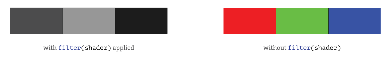
Since the sketch currently doesn’t contain any drawing functions so far, we won’t have anything to render and modify. Let’s add a few colorful rectangles to the screen and then apply the shader to see how it will affect the image. Let’s add this code within the draw() function before the filter() function is called:
void draw() {
  background(255);
  fill(255, 0, 0);
  rect(0, 0, 200, height); // add a red rectangle
  fill(0, 255, 0);
  rect(200, 0, 200, height); // add a green rectangle
  fill(0, 0, 255);
  rect(400, 0, 200, height); // add a blue rectangle
  filter(shader);
}
Here’s the result of this updated sketch running with and without the shader being applied:
You can try modifying the values within the calculation part of the shader to see how each color is being converted to grayscale:
// Play with these numbers and notice the grayscale changes
float gray = 0.299*normalColor.r + 0.587*normalColor.g + 0.114*normalColor.b;
You might think that converting a color image to grayscale is no big deal since you can do the same with Processing’s built in GRAY() filter. The most compelling reason to use shaders is that they would be an order of magnitude faster than CPU intensive filter operations. This is especially true when it comes to animation or video.
Let’s take the same shader and apply it to a live camera feed using the GL Video class!
Using a shader with camera feed
Since the shader can be applied to any image coming from Processing sketch, we can put together a sketch that does the following:
- Captures the video stream from the camera
- Draws the video frames of the camera onto the screen
- Applies our grayscale shader and shows the modified video feed on the screen
The most important part of this process is to read the camera data, draw it onto a PImage object and apply the shader:
...
// setup the sketch and the camera
...

// Read camera data and apply shader
void draw() {
  background(0);
  if (video.available()) {
    video.read();
  }

  image(video, 0, 0);
  shader(grayscaleFilter);
}
Please see the video of the filter applied onto the camera stream in real time:
The complete sketch for this effect is below:
grayscale.pde
import gohai.glvideo.*;
GLCapture video;

// Define the shader
PShader grayscaleFilter;

void setup() {
  size(640, 480, P2D);

  String[] devices = GLCapture.list();
  println("Devices:");
  printArray(devices);

  // Use camera resolution of 640x480 pixels at 24 frames per second
  video = new GLCapture(this, devices[0], 640, 480, 24);
  video.start();

  // Load the shader
  grayscaleFilter = loadShader("shader.glsl");
}

void draw() {
  background(0);
  if (video.available()) {
    video.read();
  }

  image(video, 0, 0);

  // Apply the shader
  shader(grayscaleFilter);
}
Contents of the shader file: shader.glsl
// Shader that turns color image into grayscale
#define PROCESSING_TEXTURE_SHADER

uniform sampler2D texture;
varying vec4 vertTexCoord;

void main () {
  vec4 normalColor = texture2D(texture, vertTexCoord.xy);
  float gray = 0.299*normalColor.r + 0.587*normalColor.g + 0.114*normalColor.b;
  gl_FragColor = vec4(gray, gray, gray, normalColor.a);
}
This is a start! Using GL Video and shaders becomes a powerful combination to create compelling real-time visualizations. Now we can explore more advanced topics like passing parameters from the sketch to the shader.
Passing parameters to the shader
What if you wanted to change values within the shader in real time, and could pass those values from the sketch somehow? The PShader class has a single method for that, the set() method.
Using this method you can ask the sketch to update some variables within the shader in real time. For example, let’s say our shader has the following variable that acts as an array of two values:
...
uniform vec2 pixels;
...
Now, using the set() method, you could update the pixels variable within the shader by specifying what values you’d like to pass into it:
// First parameter specifies the name of the variable, followed by new values
effect.set("pixels", 0.1 * mouseX, 0.1 * mouseY);
Let’s take a look at how this can be used in practice:
Here’s the shader code:
pixelate.glsl
#ifdef GL_ES
precision mediump float;
precision mediump int;
#endif

#define PROCESSING_TEXTURE_SHADER

// From Gene Kogan's Github Repo https://github.com/genekogan/Processing-Shader-Examples/tree/master/TextureShaders/data

varying vec4 vertTexCoord;
uniform sampler2D texture;
uniform vec2 pixels;

void main(void)
{
    vec2 p = vertTexCoord.st;

  p.x -= mod(p.x, 1.0 / pixels.x);
  p.y -= mod(p.y, 1.0 / pixels.y);

  vec3 col = texture2D(texture, p).rgb;
  gl_FragColor = vec4(col, 1.0);
}
And here is the Processing sketch:
import gohai.glvideo.*;
GLCapture video;

PShader effect;

void setup() {
  size(640, 480, P2D);

  String[] devices = GLCapture.list();
  println("Devices:");
  printArray(devices);

  // Use camera resolution of 640x480 pixels at 24 frames per second
  video = new GLCapture(this, devices[0], 640, 480, 24);
  video.start();

  effect = loadShader("pixelate.glsl");
}

void draw() {
  background(0);
  if (video.available()) {
    video.read();
  }

  effect.set("pixels", 0.1 * mouseX, 0.1 * mouseY);

  image(video, 0, 0);
  shader(effect);
}
The variable pixels within the shader is updated from the sketch with the coordinates of the mouse movement and is then reflected in the shader by these lines:
p.x -= mod(p.x, 1.0 / pixels.x); // pixels.x is 0.1 * mouseX in the sketch
p.y -= mod(p.y, 1.0 / pixels.y); // pixels.y is 0.1 * mouseY in the sketch
There are many types of variables that you can pass from the sketch to the shader code so be sure to check the reference for the set() method
Another sketch that uses the same method to update shader variables is the Halftone effect. Here’s a short demo:
Here’s the shader code:
halftone.glsl
#ifdef GL_ES
precision mediump float;
precision mediump int;
#endif

#define PROCESSING_TEXTURE_SHADER

// From Gene Kogan's https://github.com/genekogan/Processing-Shader-Examples/tree/master/TextureShaders/data

varying vec4 vertTexCoord;
uniform sampler2D texture;
uniform int pixelsPerRow;

void main(void)
{
  vec2 p = vertTexCoord.st;
  float pixelSize = 1.0 / float(pixelsPerRow);

  float dx = mod(p.x, pixelSize) - pixelSize*0.5;
  float dy = mod(p.y, pixelSize) - pixelSize*0.5;

  p.x -= dx;
  p.y -= dy;
  vec3 col = texture2D(texture, p).rgb;
  float bright = 0.3333*(col.r+col.g+col.b);

  float dist = sqrt(dx*dx + dy*dy);
  float rad = bright * pixelSize * 0.8;
  float m = step(dist, rad);

  vec3 col2 = mix(vec3(0.0), vec3(1.0), m);
  gl_FragColor = vec4(col2, 1.0);
}
And here’s the Processing sketch:
import gohai.glvideo.*;
GLCapture video;

PShader effect;

void setup() {
  size(640, 480, P2D);

  String[] devices = GLCapture.list();
  println("Devices:");
  printArray(devices);

  // Use camera resolution of 640x480 pixels at 24 frames per second
  video = new GLCapture(this, devices[0], 640, 480, 24);
  video.start();

  effect = loadShader("halftone.glsl");
}

void draw() {
  background(0);
  if (video.available()) {
    video.read();
  }

  // Change pixelsPerRow variable within the shader depending on mouse position
  effect.set("pixelsPerRow", (int) map(mouseX, 0, width, 2, 100));

  image(video, 0, 0);
  shader(effect);
}
Since the dynamic parameters can come from anywhere within the sketch, you can get even more creative and not stop at using the mouse or keyboard to input the new values for the parameters. Some other alternatives that work on the Pi are:
- Knobs (potentiometers via analog to digital conversion)
- Buttons
- Sliders
- Capacitive touch
- HTTP requests
With these basic principles covered, you can now explore more shaders on your own!
Resources
Try out some of the shaders that are open source with Processing in mind:
- Cacheflowe’s Haxademic repository
- Filters4Processing
- Shadershop
- Gene Kogan’s Shaders for Processing
There are many websites and online communities that serve as repositories of GLSL shaders and there are many open source shaders in the wild that you can use with some minor effort to make them work in Processing. Some websites like that are:
- Shadertoy (https://www.shadertoy.com/)
- GLSL Sandbox (http://glslsandbox.com/)
- Interactive Shader Format (https://www.interactiveshaderformat.com)
Next steps
There are so many things that can be done with the concepts covered in this tutorial! You can use GL Video library to work with some other built in Processing sketches like these and can get really creative inventing your own ways to visualize camera feed. Please let me know what you come up with and feel free to share with me on Twitter: @msurguy
Using a push button for shutter
In case you want to use a physical push button to save the frame from the video feed, you can use the following sketch:
// Sketch for shutter button. The button should be connected to pin 4 on the Pi
import processing.io.*;
import gohai.glvideo.*;
GLCapture camera;

void setup() {
  size(640, 480, P2D); //or use fullScreen(P2D);
  String[] devices = GLCapture.list();
  camera = new GLCapture(this, devices[0], 640, 480, 30);
  camera.start();

  // Add a button on pin 4, see the "Visual Synthesizer" tutorial for more information
  GPIO.pinMode(4, GPIO.INPUT_PULLUP);
}

void draw() {
  background(0);
  if (camera.available()) {
    camera.read();
  }
  image(camera, 0, 0, width, height);

  // When the button is pressed, take a picture
  if (GPIO.digitalRead(4) == GPIO.LOW) {
    saveFrame("CAP####.jpg");
    delay(500);
  }
}
Appendix
GL Video library installation and set up
If you’re not using the pre-configured image for the Pi, you’ll need to install the GL Video library and enable the camera.
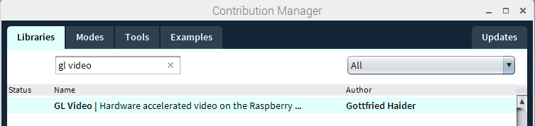
To use GL Video Library in Processing on the Pi, find it in the contribution manager and install it:
There are two types of cameras that GL Video can work with:
- Raspberry Pi Camera
- USB webcams
Now, let’s look at the setup required if you’ll be using the Pi Camera.
If using the Pi Camera
If it is the first time you Pi Camera on the Pi, some preliminary steps are needed in order to use the camera with Procesing:
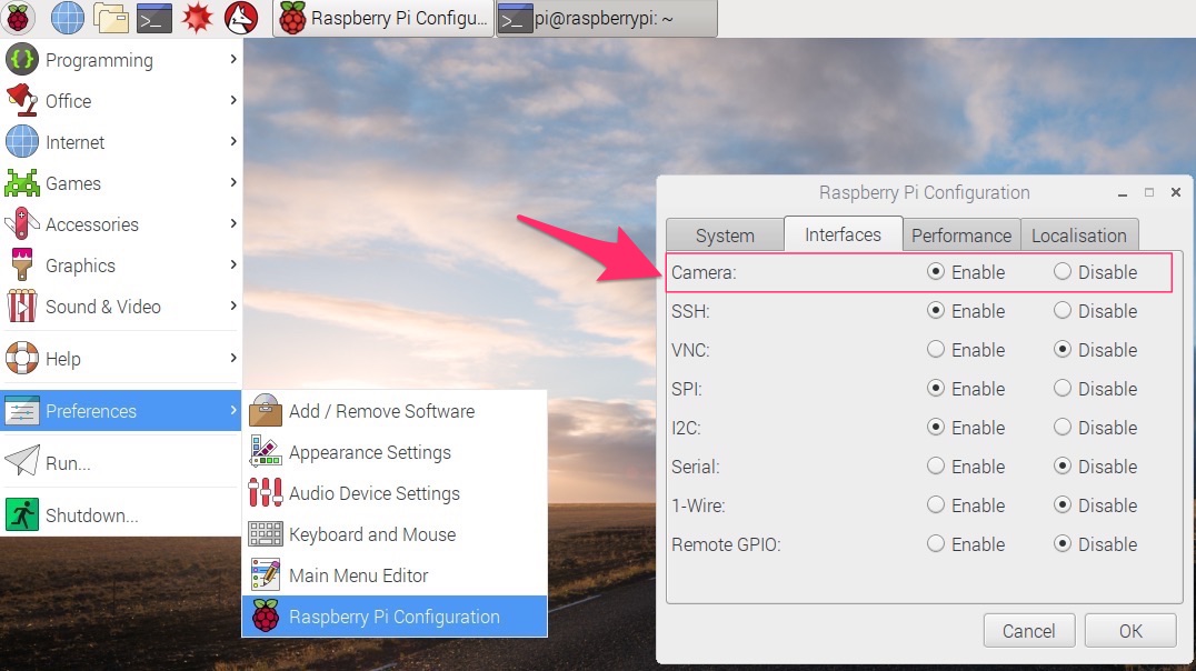
- Enabling the camera interface using GUI tool or
raspi-configcommand line tool - Connecting the camera
- Enabling
bcm2835_v4l2driver
You can use Raspbian’s built-in configuration tool to enable the camera interface. Click on the launcher in top left, then navigate to Preferences -> Raspberry Pi Configuration -> Interfaces, and enable the camera interface:
Now, turn off the Pi and connect the camera to the CSI interface. After the camera is connected, you can boot up the Pi and perform one more step of the setup.
GL Video library needs a special driver to be enabled on the operating system level. Add the line "bcm2835_v4l2" (without quotation marks) to the file /etc/modules. This can be accomplished by executing the following in a terminal window:
echo "bcm2835_v4l2" | sudo tee -a /etc/modules >/dev/null
After a restart you should be able to use the Pi Camera in Processing!