Visual Synthesizer
Introduction
Integrating low cost hardware components with Processing software paves the way for creating compelling human-computer interactions. Processing’s ease of use to create visual representations and Raspberry Pi’s established ecosystem make this combination a perfect match for education, arts and science.
The visual synthesizer (synth) project aims to introduce you to combining interactive features of Processing with access to the physical world through the input / output capacity of the Raspberry Pi and a few additional hardware components.
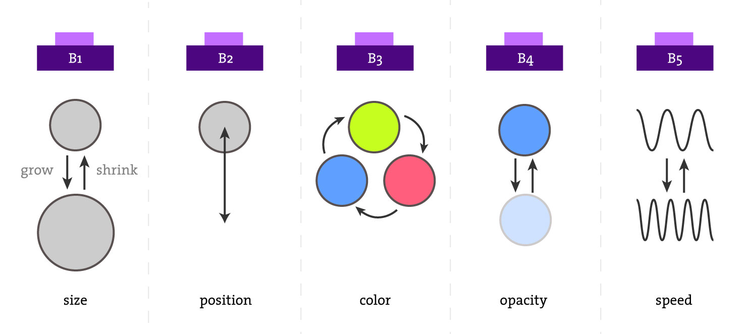
In this project, a few physical buttons are connected to a Raspberry Pi. A person pressing these buttons can control the following parameters of objects inside of a Processing sketch that’s running on the Pi:
- Size
- Position
- Color
- Opacity
- Speed
Depending on which buttons are pressed, various object parameters will be affected, as demonstrated in the video of the final sketch of this tutorial:
Video of the visual synth sketch running on Raspberry Pi:
By following the steps below you will get an overall understanding of how to use Raspberry Pi and Processing together to create an interactive experience. Using this knowledge, you could create more complex interactive systems or modify your existing Processing sketches to work with simple hardware described in this tutorial.
Concepts covered
The projects touches upon the following concepts:
- Making breadboard prototypes
- Accessing General Purpose Input/Output (GPIO) pins of the Raspberry Pi using Processing’s Hardware I/O library
- Using push buttons with Processing
Getting started
In order to get started, you would need a Raspberry Pi with Processing installed. The code shown in this tutorial needs to run within Processing Development Environment on the Raspberry Pi in order to work with the hardware pins of the Pi. The tutorial is written for users with various technical backgrounds so please keep that in mind as you replicate the project.
With that, let’s gather the components and get coding!
Project Materials
In order to complete this tutorial, you would need the following items:
- a Raspberry Pi model 3+, 3 or 2 (those are recommended, it will work the Pi Zero and older versions, albeit much more slowly) with Processing installed
- TV or any screen / monitor with HDMI input
- 1-5 push buttons
- Breadboard
- Wires
History and Background information
An optional introduction to buttons.
For almost two hundred years, buttons have been one of the most commonly used methods of interfacing with technology. The underlying principle of a button is simple and well-suited for anything where there’s electricity present: completing or breaking a circuit when the button is pressed. Thanks to this functional simplicity, use of buttons as interaction method gained wide popularity. They’ve been used to do mundane and great things alike: from making it possible to type up Morse code via telegraph in the early 1800’s, ringing household bells in early 1900’s, switching TV channels in 1950’s, to launching huge rockets into space!
Nowadays we encounter buttons dozens or hundreds of times a day, sometimes without realizing it. Pressing a button is usually followed by some kind of feedback mechanism: a sound, changing light, message on a screen, etc. We often take this interaction for granted and are surprised when pushing a button doesn’t produce any sort of feedback or response.
An optional introduction to synthesizers.
A synthesizer is an electronic instrument producing a variety of sounds by generating and combining signals of different frequencies.
Synthesizers usually have a number of keys, buttons, knobs and/or sliders that affect some parameters of the sound or trigger some changes in the synthesizer’s settings.
One of the earliest synthesizers is “Musical Telegraph” invented by Elisha Gray in 1874. After gaining wide spread popularity in 1960s within pop music industry, many artists started to use synthesizers to express creativity.
In this project we will leverage the physical feeling or pressing a button and the drawing capacity of Processing to make an unusual synthesizer: a visual synthesizer.
Types of buttons
There are few different types of buttons out there, with these two being the most commonly used:
- Push buttons (also called “Momentary push buttons” or “Momentary switches”)
- Microswitches
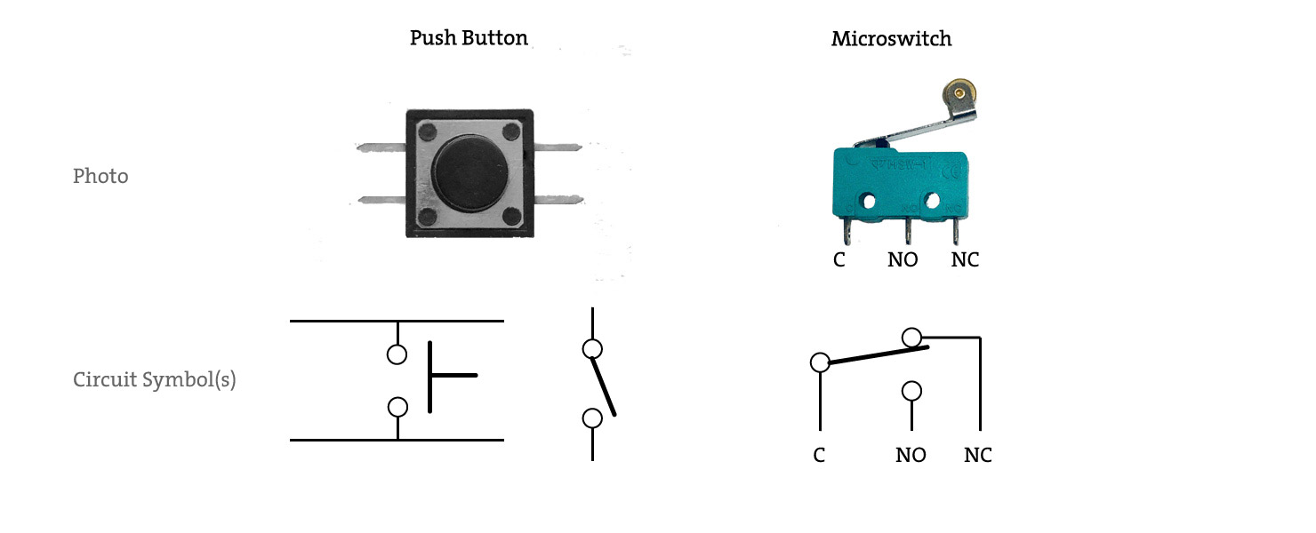
Within these types, the connections inside the buttons could be:
- Normally Closed
- Normally Open
In this tutorial, we’ll be using the most common type of button: Normally Open Push Buttons.
Raspberry Pi GPIO and Processing
Modern Raspberry Pi computers have 26 pins that can be designated to be an input (receiving signals) or output (sending signals) pins. 9 of those are shared between other interfaces (I2C, SPI, UART), leaving 17 pins that can be used purely for input and output. Here’s a diagram showing the GPIO pins that are not shared with other interfaces on the Raspberry Pi:

Processing’s built in Hardware I/O Library (processing.io.*) can work with any of the GPIO pins to read signals or output signals on those pins.
Before using the GPIO pins in your sketch, you must determine whether the pin will be used as an input (e.g. reading button state) or as an output (e.g. turning on an LED) and configure the pin by using Hardware I/O library’s GPIO.pinMode function (reference). When the pin is set as an input, there are three different options for it’s pinMode to choose from:
- INPUT
- INPUT_PULLDOWN
- INPUT_PULLUP
Using one of these three options determines whether a pull-up / pull-down resistor is enabled on that particular pin or if the default state of the circuitry of the Raspberry Pi should be used, which is not recommended.
After the pin is configured to act as an input with a pull-down or pull-up resistor, we can get the current state of the button in Processing by using digitalRead function. Here is an example using a built-in pull-up resistor and retrieving the state of the button:
// Example using a built-in pull-up resistor on a Raspberry Pi GPIO pin
import processing.io.*;

int buttonPin = 4; // The button is connected to pin 4 and ground

void setup() {
  GPIO.pinMode(buttonPin, GPIO.INPUT_PULLUP);
}
...
// Because a pull-up resistor is enabled, the button will read LOW when it's pressed
if (GPIO.digitalRead(buttonPin) == GPIO.LOW) {
  // Button is pressed
}
If we used a pull-down resistor, the button would need to be connected to +3.3V instead of one of the ground pins, and the Processing sketch would be as follows:
// Example using a built-in pull-down resistor on a Raspberry Pi GPIO pin
import processing.io.*;

int buttonPin = 4; // The button is connected to pin 4 and the positive 3.3V

void setup() {
  GPIO.pinMode(buttonPin, GPIO.INPUT_PULLDOWN);
}
...
// Because a pull-down resistor is enabled, the button will read HIGH when it's pressed
if (GPIO.digitalRead(buttonPin) == GPIO.HIGH) {
  // Button is pressed
}
With these basics covered, let’s move on!
Making the visual synth
Now that you know about different types of buttons, some basics about GPIO and Processing’s pinMode function, there are two main steps to make the visual synth:
- Make a single button change an object’s attribute within Processing
- Add more buttons and add more attributes that can be changed
Let’s start by connecting a single button to the Raspberry Pi and making it work with Processing!
Getting a single button to interact with Processing
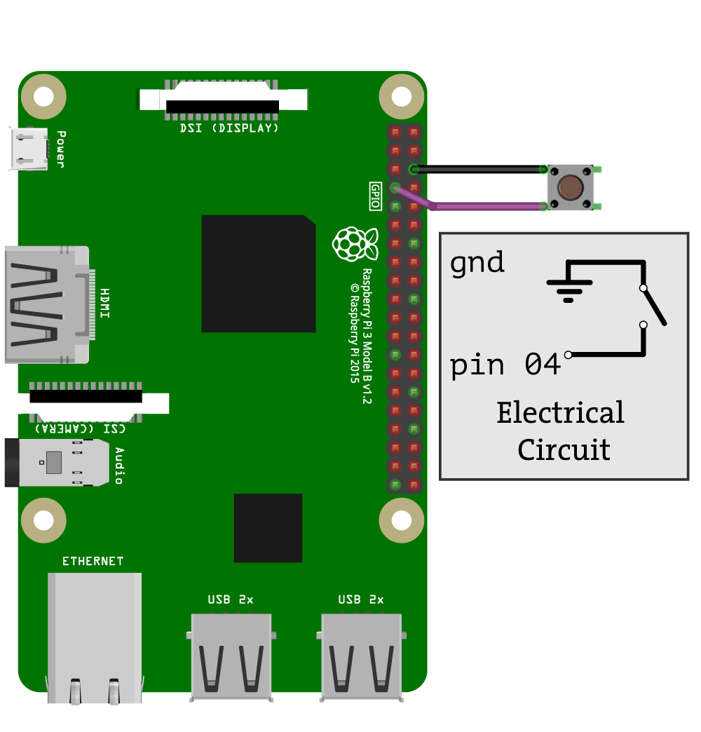
The easiest way to make a button work on Raspberry Pi is to connect it between a GPIO pin and one of the ground pins. In order for this to register as an input when the button is pressed, an internal pull-up resistor has to be enabled.
In this tutorial, we’ll be using the INPUT_PULLUP mode for the input pins and this way avoid using other components like external resistors.
Let’s connect a single button to GPIO pin #4 and ground as shown in the schematic:
With this simple electrical circuit in place, we can create a basic sketch in Processing that will use the state of the button as the input. In this sketch, let’s fill in a circle when the button is pressed, and let’s make the circle empty when it’s not:
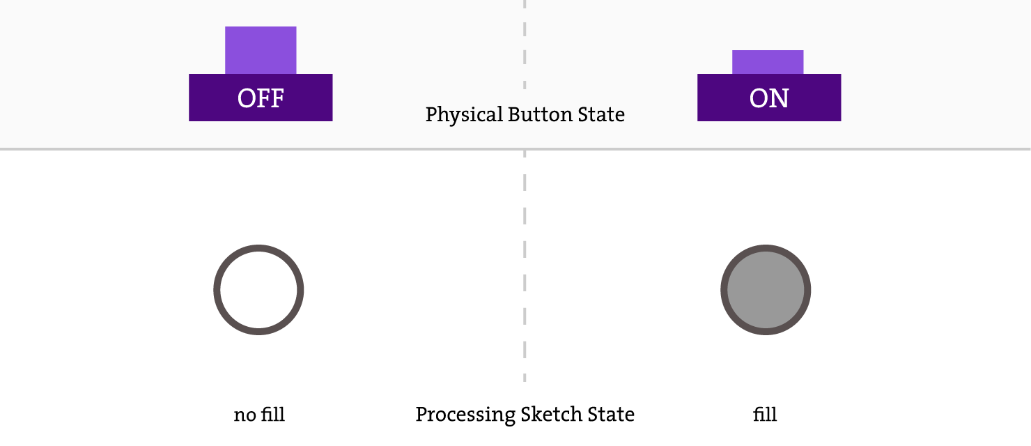
The Processing sketch for this basic interaction comes with the built-in examples of the Hardware I/O library and is presented below:
// Button event processing example

import processing.io.*;

// GPIO numbers refer to different phyiscal pins on various boards
// On the Raspberry Pi GPIO 4 is physical pin 7 on the header
// see setup.png in the sketch folder for wiring details

int buttonPin = 4;

void setup() {
  // INPUT_PULLUP enables the built-in pull-up resistor for this pin
  // left alone, the pin will read as HIGH
  // connected to ground (via e.g. a button or switch) it will read LOW
  GPIO.pinMode(buttonPin, GPIO.INPUT_PULLUP);
}

void draw() {
  // sense the input pin
  if (GPIO.digitalRead(buttonPin) == GPIO.LOW) {
    fill(255);
  } else {
    fill(204);
  }

  stroke(255);
  ellipse(width/2, height/2, width*0.75, height*0.75);
}
We can use this simple circuit and the sketch as the basis for the next steps in making the visual synth!
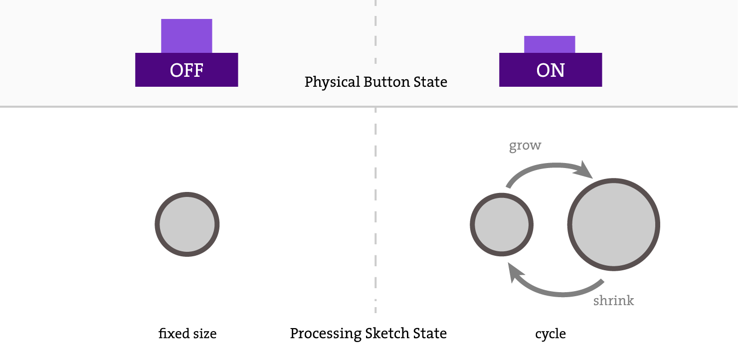
Our goal is to make something within Processing to react to the state of the button continuously. When the button is not pressed, we want the object to remain the same, but when the button is pressed, we’d like the object to continuously react for the entire time the button is pressed. For example, if the button is pressed, the object can expand, shrink and do that over and over until the button is released. Here’s a diagram that shows those two different stages:
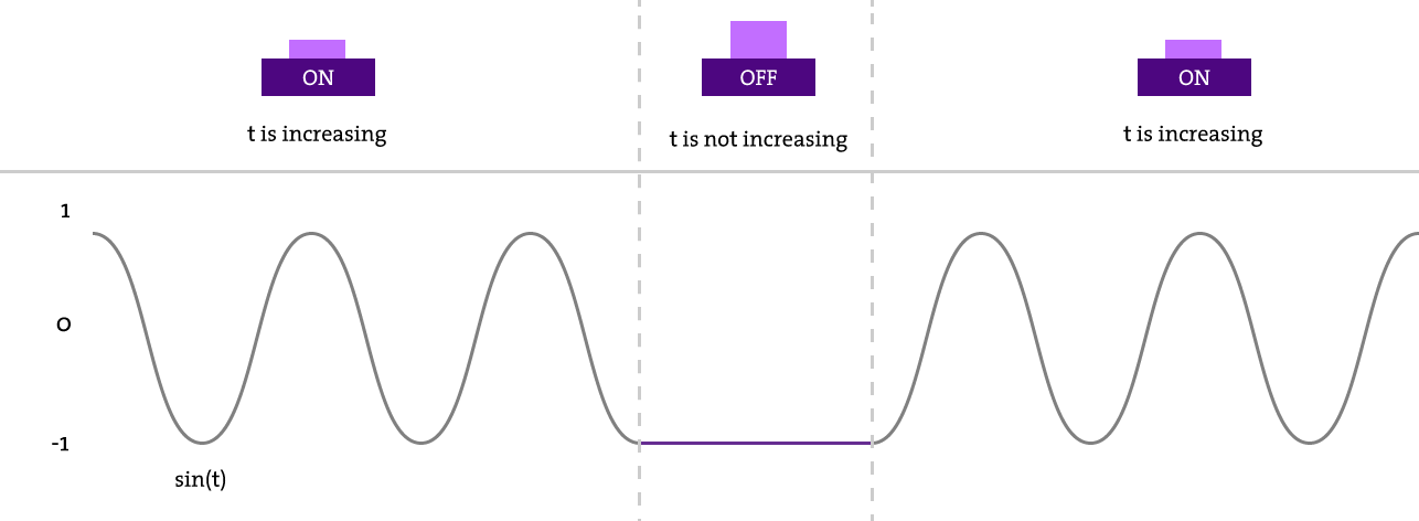
To achieve this cyclical growing/shrinking animation cycle, we can use the concept of “oscillator” that comes from audio synthesizers.
The base for our oscillator will be a sinusoidal wave created with Processing sin(x) function. We can create an internal counter that will be incremented only when the button is pressed and feed the value of that counter to the sin(x) function:
Let’s try this out in practice and make a simple sketch demonstrating the cyclical growing and shrinking during button press:
import processing.io.*;

int buttonPin = 4;           // Which pin the button is connected to
int circleDiameter = 200;    // Original diameter of the circle
float updatedCircleDiameter; // This holds growing / shinking diameter
int circleGrowthDelta = 50;  // Max growth increase
float t = 0.0;                 // Counter for the oscillator

void setup() {
  size(400, 400);
  GPIO.pinMode(buttonPin, GPIO.INPUT_PULLUP);
}

void draw() {
  background(100);

  // Increase the counter when button is pressed
  if (GPIO.digitalRead(buttonPin) == GPIO.LOW) {
    t += 0.06;
  }

  fill(180);
  stroke(255);

  updatedCircleDiameter = circleDiameter + circleGrowthDelta * (sin(t));
  ellipse(width/2, height/2, updatedCircleDiameter, updatedCircleDiameter);
}
When running this sketch, you should see a circle that’s only growing and shrinking when the button connected to pin 4 is pressed! Now that we have the concept of oscillator figured out and working, let’s move on to the next step and tie everything together!
Adding more buttons
Since we have one type of attribute change working, why not add more interesting object modifiers? You can explore other use cases for the oscillator, but we thought that these modifiers would demonstrate the synth capabilities well:
- Position
- Color
- Opacity
- Speed of changes
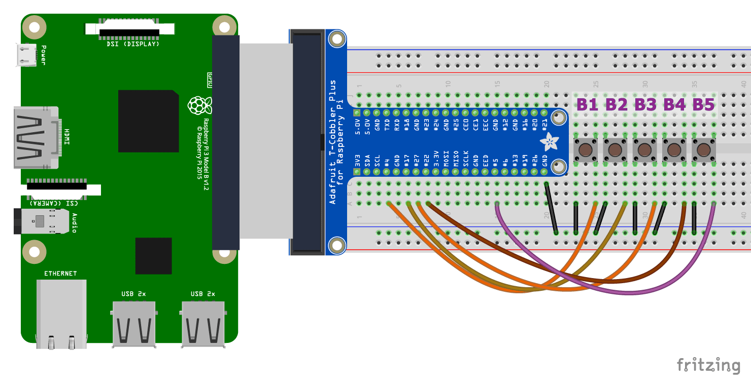
The same way as we connected a single button, we can connect many more buttons (a total of 26 can be connected) to the GPIO pins. For the synth we only need 5 in total, so let’s connect them to the following GPIO pins and ground:
- pin 04
- pin 17
- pin 27
- pin 22
- pin 5
The connection diagram is presented below:
With this connection in place, let’s test all of our buttons first by simply printing some text in the console:
// Import Processing's Hardware library
import processing.io.*;

void setup() {
  size(400, 400);

  // Set the five pins as inputs with pullup resistors turned on:
  GPIO.pinMode(4, GPIO.INPUT_PULLUP);
  GPIO.pinMode(17, GPIO.INPUT_PULLUP);
  GPIO.pinMode(27, GPIO.INPUT_PULLUP);
  GPIO.pinMode(22, GPIO.INPUT_PULLUP);
  GPIO.pinMode(5, GPIO.INPUT_PULLUP);
}

void draw() {
  if (GPIO.digitalRead(4) == GPIO.LOW) {
    println("Pin 4 is currently active")
  }

  if (GPIO.digitalRead(17) == GPIO.LOW) {
    println("Pin 17 is currently active")
  }

  if (GPIO.digitalRead(27) == GPIO.LOW) {
    println("Pin 27 is currently active")
  }

  if (GPIO.digitalRead(22) == GPIO.LOW) {
    println("Pin 22 is currently active")
  }

  if (GPIO.digitalRead(5) == GPIO.LOW) {
    println("Pin 5 is currently active")
  }
}
If the buttons are working, you are ready to finish putting the synth together!
Complete Sketch
For the final sketch, we’ll create an object “Circle” with attributes and parameters that will be affected by the buttons. When any of the buttons are pressed, an internal counter will be incremented, leading to a change in sin() values that will then increase / decrease one of the circle’s attributes. The sketch below implements the visual synth functionality:
// Import Processing's Hardware library
import processing.io.*;

// Define an instance of the Circle object
Circle myCircle;

// Define the pins that will be reading button presses
int[] pins = { 4, 17, 27, 22, 5 };

void setup() {
  size(400, 400);
  // Change the color mode of the sketch to HSB
  colorMode(HSB, 360, 100, 100);
  noStroke();

  // INPUT_PULLUP enables the built-in pull-up resistor for this pin
  // left alone, the pin will read as HIGH
  // connected to ground (via e.g. a button or switch) it will read LOW

  // Set all pins in the pins array as inputs with pull-up resistors enabled
  for (int i = 0; i < pins.length; i++) {
    GPIO.pinMode(pins[i], GPIO.INPUT_PULLUP);
  }

  // Create a circle in the middle of the screen
  myCircle = new Circle(width / 2, height / 2, 100, 148);
}

void draw() {
  background(0);

  // Modify attributes of the circle depending on which buttons are pressed
  if (GPIO.digitalRead(pins[0]) == GPIO.LOW) {
    myCircle.pulsateSize();
  }
  if (GPIO.digitalRead(pins[1]) == GPIO.LOW) {
    myCircle.pulsatePosition();
  }
  if (GPIO.digitalRead(pins[2]) == GPIO.LOW) {
    myCircle.pulsateHue();
  }
  if (GPIO.digitalRead(pins[3]) == GPIO.LOW) {
    myCircle.pulsateOpacity();
  }

  // Increase the speed of the animation while the 5th button is pressed
  if (GPIO.digitalRead(pins[4]) == GPIO.LOW) {
    myCircle.speed(0.12);
  } else {
    myCircle.speed(0.06);
  }

  // Update the circle state
  myCircle.update();
  // And draw it to the screen
  myCircle.display();
}

class Circle {

  // These variables store the initial position of the circle
  float originalXpos;
  float originalYpos;
  // These store its current position
  float xpos;
  float ypos;
  // Possible deviation from the initial position, in pixels
  int orbitRange = 50;

  float originalDiameter;
  float diameter;
  int growthRange = 50;

  int opacity = 255;
  int opacityRange = 80;

  int originalHue;
  int hue;
  int hueRange = 80;

  float t = 0.0;
  float speed = 0.06;

  Circle(float x, float y, float dia, int h) {
    originalXpos = x;
    originalYpos = y;
    xpos = x;
    ypos = x;

    originalDiameter = dia;
    diameter = dia;

    originalHue = h;
    hue = h;
  }

  void pulsateSize() {
    diameter = originalDiameter + growthRange * sin(t);
  }

  void pulsatePosition() {
    ypos = originalXpos + orbitRange * cos(t*2);
  }

  void pulsateHue() {
    hue = int(originalHue + hueRange * sin(t));
  }

  void pulsateOpacity() {
    opacity = int(170 + opacityRange * sin(t));
  }

  void speed(float s) {
    speed = s;
  }

  void update() {
    t += speed;
  }

  void display() {
    fill(hue, 100, 100, opacity);
    ellipse(xpos, ypos, diameter, diameter);
  }
}
When running this sketch, you should see the properties of the circle change whenever you press any or all buttons!
We hope you enjoyed making the visual synth and enjoy playing with it!
Next Steps
There are many things you could do now to take this project forward. Here are some ideas:
- Make a nice box and put this whole system in it
- Add synth-like functionality to any of your other Processing projects
- Add more buttons and make them do more things (take a picture, add more objects, etc)
Resources
Here are some additional resources about GPIO and Raspberry Pi:
- Complete Pinout for the Raspberry Pi: https://pinout.xyz