Capacitive Touch Interface
Introduction
Would you like to escape the use of conventional input methods such as keyboard and mouse for interacting with your Processing sketches? You can make the interactivity within your skethces a lot more interesting by using capacitive touch sensing.
Capacitive touch sensing works by means of continuously measuring changes in capacitance of certain points of contact (electrodes) within a specially-designed circuit. Human body acts as an electrical insulator, capable of changing electrical capacitance of a circuit when touching the electrodes and this change in capacitance can be captured by a sensor. There are many devices that use this technology in one form or another. Touchscreens and touchpads use capacitive touch sensing to detect the position and proximity of fingers interacting with them.
In context of creative programming and physical computing, capacitive touch sensing can serve as a unique alternative to buttons because it enables the use of arbitrary shapes and sizes of conductive surfaces to act as inputs.
With addition of an inexpensive capacitive touch integrated circuit (IC) such as MPR121, your Raspberry Pi can become a breeding ground for unique interaction ideas.
In the context of this project, merely detecting when something conductive is touched or not touched by a human can enable us to make some new forms of interaction. Take a look at the video below to see how capacitive touch can be used with Processing to make a custom musical interface:
Excited to try this out? Let’s take a look at what you’ll need in order to make use of capacitive touch sensing in your sketches!
Project materials:
To build a capacitive touch musical interface or a similar input device, you would need to acquire a capacitive touch IC, specifically MPR121 that is available from Adafruit, eBay or other vendors for under $10. Here’s a full list of materials that you would need to have:
- a Raspberry Pi model 3+, 3 or 2 (those are recommended, it will work the Pi Zero and older versions, albeit much more slowly) with Processing installed
- TV or any screen / monitor with HDMI input
- MPR121 12-key Capacitive Touch Sensor Breakout
- Copper tape or any other conductor to create capacitive touch electrodes
- Headphones or a speaker with integrated amplifier
- Alligator clips or soldering iron with solder depending on what material for the electrodes you’ll be using
- Breadboard
- Wires
With these components on hand, let’s take a look how to take advantage of using a special hardware interface (I2C) to communicate with MPR121 capactive touch sensor.
Using I2C interface in Processing on Raspberry Pi
Raspberry Pi and similar single board computers support I2C interface for communicating with a wide variety of affordable integrated circuits (ICs) and peripherals that support I2C protocol. This protocol is very robust and is convenient because it requires only two wires for data exchange and multiple devices using the protocol can share the same set of wires.
How is this interface used in practice? Let’s say you have an IC or a board that is I2C compatible. You’d identify 4 pins necessary to connect it to the Raspberry Pi’s I2C pins:
- Positive power (+3.3V)
- Ground
- Serial Clock (SCL)
- Serial Data (SDA)
Then, connect those pins as follows:
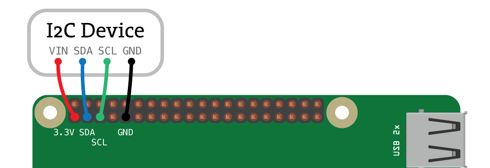
With this connection in place, you can use the I2C interface on Raspberry Pi to communicate with the I2C device. The I2C interface is supported in Processing via Hardware I/O library’s I2C class documented here: Hardware I/O I2C Reference.
To make Processing compatible with a wide variety of I2C devices on single board computers, the Hardware I/O library comes with a few useful examples (listed on Github or under “Examples > Libraries > Hardware I/O” within PDE):
- BME280 Temperature, Pressure and Humidity sensor
- MCP4725 Digital to Analog Converter (DAC)
- TSL2561 Luminosity/Lux/Light sensor
- PCA9685 PWM/Servo Driver
- MPR121 Touch sensor
- HMC6352 Compass
- SSD1306 OLED Display
In this tutorial, we’ll make use of MPR121 touch sensor example code and build on top of it to make something interesting! Now that you have some idea of how the capacitive sensing works and how to connect an I2C peripheral, let’s go through a quick overview of how to generate sound in Processing.
Generating sound in Processing
Processing is capable of playing music, generating and analyzing sounds through the use of one of the external sound libraries. In this tutorial, we’ll be using the New Sound Library by Kevin Stadler that was written as a part of Google Summer of Code 2018.
You can download the Sound Library by using the Contribution Manager within Processing:
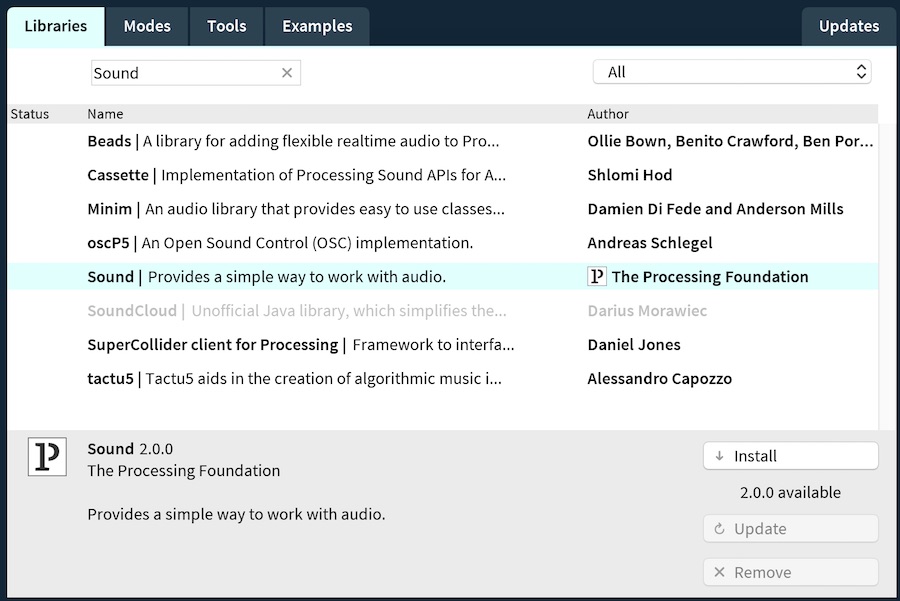
With the library installed, feel free to take a look at some of the examples included with it. We will use the concepts of “oscillators” from the Sound library to synthesize various sounds.
Now that we have the main components and concepts covered, let’s get to making your own capacitive touch musical interface!
Making the capacitive touch musical interface
In the course of the next steps of this tutorial, you’ll gradually build a synthesizer with a custom capacitive touch interface. To get there, we will first connect the MPR121 sensor to Raspberry Pi, visualize its readings in a Processing sketch, learn to synthesize sounds via the sound library, and finally, put everything together!
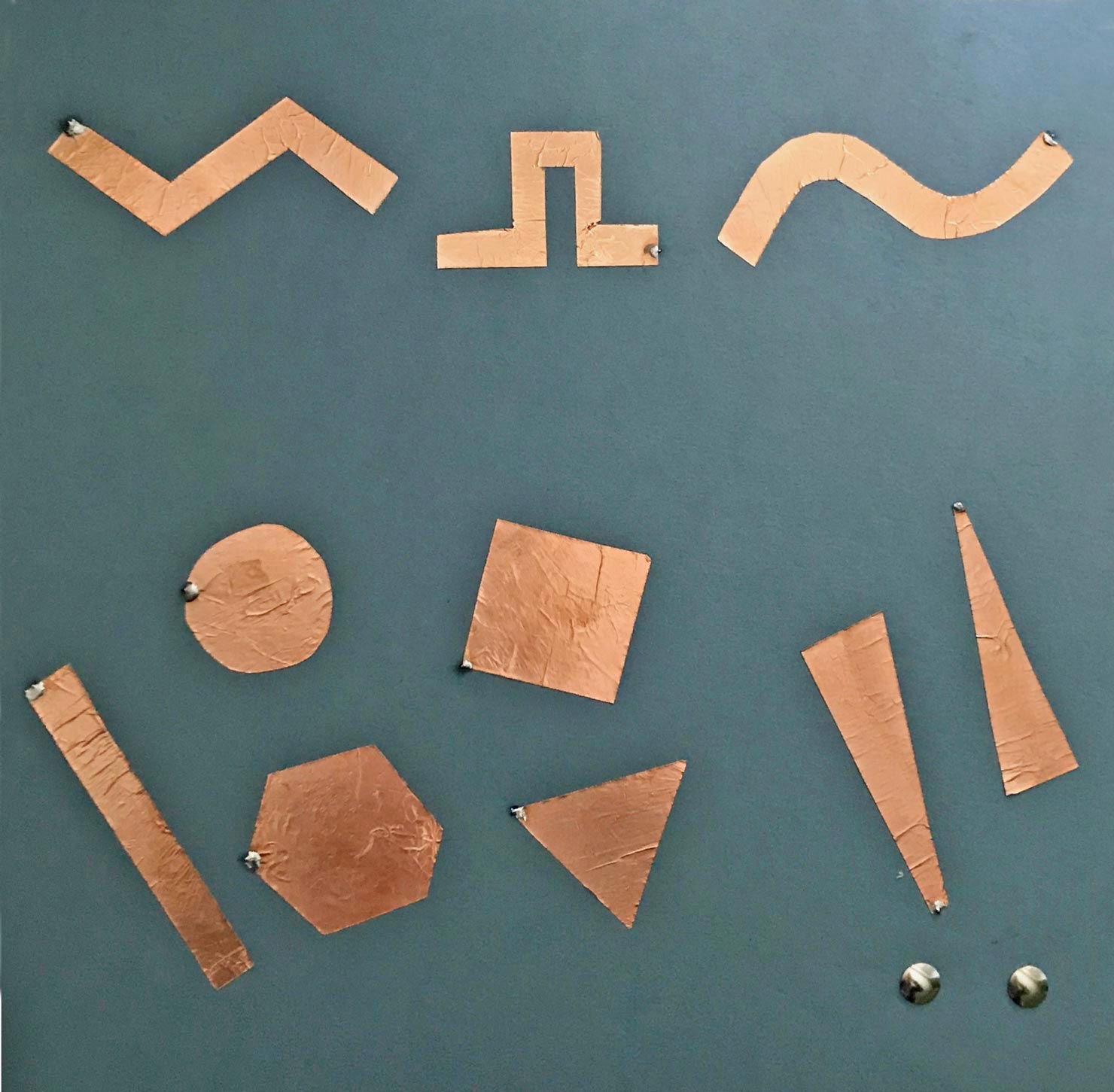
I used cardboard and sticky backing copper tape to create the following interface layout, but of course you’ll be free to make your own arrangement:
Here’s the suggested order of the steps to build your custom synthesizer:
- Connecting MPR121 sensor breakout board
- Using an example sketch to create visual representation of the touch sensor state
- Responding to touch by synthesizing sounds
- Using advanced features of MPR121 sensor to affect pitch
- Putting everything together
Let’s connect the capacitive touch sensor to the Raspberry Pi!
1. Connecting MPR121 capacitive touch sensor
MPR121 is I2C capable microcontroller, and like any I2C chip, it can be easily connected to Raspberry Pi via four wires:
- Power pin (3.3V)
- Ground pin
- SDA pin
- SCL pin
Below you’ll find a diagram of how to connect the MPR121 breakout board to Raspberry Pi:
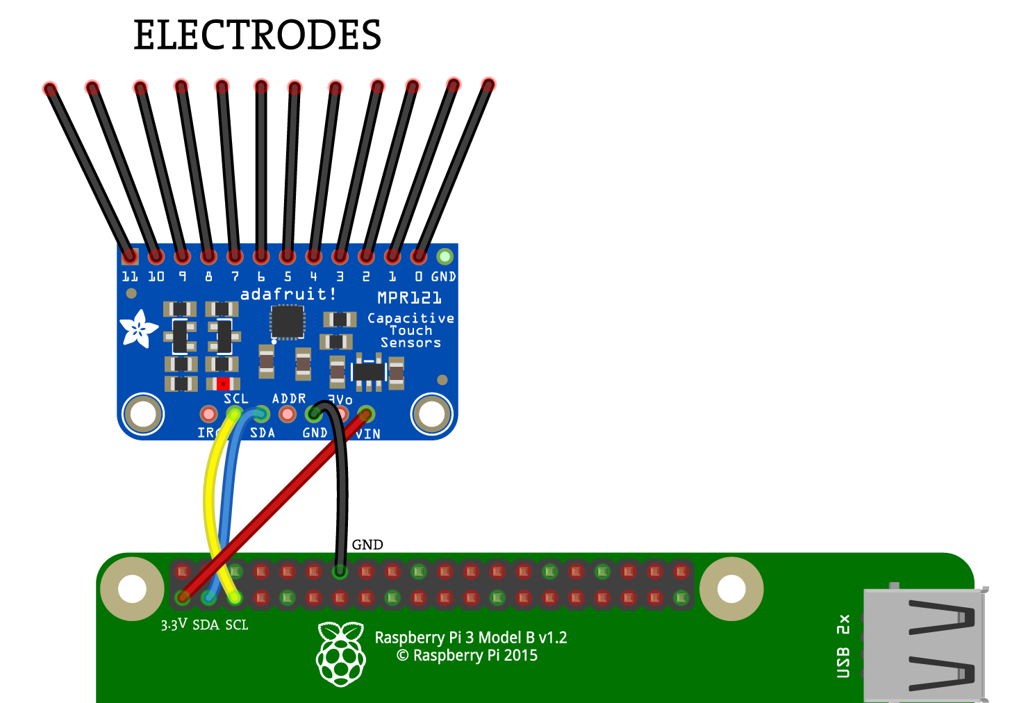
When the MPR121 board is connected to the Raspberry Pi, you can start experimenting with making and connecting the electrodes that you’ll use to interact with the rest of the Processing sketches in this tutorial. For the final sketch of this tutorial, you’ll need all 12 electrodes to be connected to the MPR121 board but you don’t need all 12 right now.
For now, you can just connect 2-3 breadboarding wires to the first few electrode pins of the MPR121 breakout board.
What to use for the electrodes
What can you use to make the electrodes? Basically anything that conducts electricity to some degree should work well. Here’s a list of some things you can try with MPR121 sensor:
- Wires
- Printed Circuit Boards
- Copper / Aluminum foil
- Salt water
- Tap water
- Conductive tape
- Conductive thread
- Conductive fabric
- Conductive 3D printer filament(!)
- Organic materials such as fruit and vegetables
Sensors like MPR121 provide a lot of creative freedom in what arrangements and materials you can use to communicate with objects in your Processing sketches. Let’s experiment with reading the MPR121 sensor data in the next steps.
2. Visualizing the state of MPR121 sensor
First, let’s try one of the built-in examples to visualize which electrodes are being touched. The Touch_I2C_MPR121 example sketch mentioned above has some starter code that we will use for the next steps of the tutorial. Please find and open this sketch from the “Examples” window:
When you run this sketch, you’ll see the white dots on the screen, representing the state of each electrode connected to the MPR121 sensor. When you touch the makeshift electrodes (breadboarding wires) connected to the pins of MPR121 sensor, you should start seeing the updates in the Processing sketch:
How does Processing track the touch state in this sketch? To get a reading from MPR121 sensor and determine whether a certain electrode is being touched or not, we need to do two things: ask the sensor to update its state by issuing a call to .update() within the draw() function and ask about the state of specific electrode on MPR121 by issuing a .touched(N) where N is the pin number we care about (can be 0-11):
void draw() {
  ...
  touch.update();
  // Check all 12 electrodes one by one
  for (int i=0; i < 12; i++) {
    if (touch.touched(i)) {
      // i-th Pin is touched
    } else {
      // i-th Pin is not touched
    }
    ...
  }
}
Now that you understand the basics of how the MPR121 sensor and MPR121 class works, let’s use it to make sound via the sound library!
3. Synthesizing sound using the Sound library
The Sound library comes with many great examples, specifically on how to synthesize sound using oscillators. Let’s take one of these examples and make it work with MPR121 touch sensor.
For now, we will be working with the SawWave oscillator and you can check out the example of using it in “Contributed Libraries -> Sound -> Oscillators -> SawWave.pde” sketch. That example sketch synthesizes a continuous sound that you can affect by moving the mouse on the screen. The main part of that sketch is the initialization of the oscillator, calling .play() on it and specifying the frequency of the oscillation:
import processing.sound.*;

SawOsc saw;

void setup() {
    ...
    // Create the sine oscillator and start synthesizing sound
    saw = new SawOsc(this);
    saw.play();
}

void draw() {
    // Map mouseY from 0.0 to 1.0 for amplitude
    saw.amp(map(mouseY, 0, height, 1.0, 0.0));

    // Map mouseX from 20Hz to 1000Hz for frequency
    saw.freq(map(mouseX, 0, width, 80.0, 200.0));
}
We will modify that sketch to change the frequency of the sound generated by the library depending on whether the first electrode connected to MPR121 sensor is touched or not (instead of using horizontal position of the mouse).
Let’s put the sound synthesis and touch sensor operations together by increasing the amplitude of the sound when the first electrode of the MPR121 is touched:

The code below shows how you would combine the sound library and the MPR121 sensor to modify the amplitude of the synthesized sound:
/**
 * This is a combination of saw wave oscillator example of the sound library and MPR121 example from I/O Hardware Library.
 * Touching pin 0 of the MPR121 sets the frequency of the oscillator to 252Hz, while not touching sets it to 500Hz.
 */

import processing.sound.*;
import processing.io.*;

MPR121 touch; // define MPR121 I2C capacitive touch sensor

SawOsc saw;

void setup() {
  size(640, 360);
  background(255);

  touch = new MPR121("i2c-1", 0x5a); // Read capacitive touch from MPR121 using its default address

  // Create and start the saw oscillator.
  saw = new SawOsc(this);
  saw.play();
}

void draw() {
  // Map mouseY from 0.0 to 1.0 for amplitude
  saw.amp(map(mouseY, 0, height, 1.0, 0.0));

  touch.update(); // get readings from the MPR121 I2C sensor

  // If electrode 0 is touched, set the frequency to 252Hz, otherwise set it to 500Hz
  if (touch.touched(0)) {
    saw.freq(252);
  } else {
    saw.freq(500);
  }
}
Currently the frequency of the sound generated by the oscillator is set by the horizontal coordinate of the mouse. What if you wanted to affect the frequency of the sound by the position of your finger on the electrode that’s being touched? MPR121 Class provides us with analogRead(pin) function that returns the capacitance value of a specific electrode.
4. Using analogRead() to affect pitch
Besides detecting whether some electrode is being touched or not, MPR121 class provides some additional features like:
- returning raw capacitance value via
analogRead(channel)function - returning raw capacitance value substracted from baseline value via
analogReadBaseline(channel)function
When the electrode connected to the MPR121 sensor is being touched, the capacitance value measured by MPR121 can be different depending on where exactly the electrode is being touched. Because of this behavior, analogRead() and analogReadBaseline() can be used to add some more control of the Processing sketch. While it doesn’t provide us with precise control, this feature allows us to add some variation within the frequencies of the sound generated by the oscillators.
Let’s use the analogRead() function of the MPR121 class to make something that functionally resembles a pitch wheel on a synthesizer. Using the last sketch of this tutorial, we will change the default frequency of the oscillator from mouse-position dependent to finger-position dependent:
// Old (using horizontal mouse position):
float frequency = map(mouseX, 0, width, 20.0, 1000.0);
saw.freq(frequency);

// New (using touch.analogRead on pin 0):
float frequency = map(touch.analogRead(0), 0, 200, 100.0, 1000.0);
saw.freq(frequency);
With this simple change, the frequency of the sound will be changed depending on how far along the electrode the touch is occurring. Try experimenting by moving the finger along the electrode and listen to the changing sound!
5. The Final Sketch
Now that you have good understanding of interfacing with MPR121 touch sensor and using the sound library to synthesize sound, let’s create a custom musical interface that incorporates all of those concepts.
Here’s what we will do:
- Envision how the musical interface will look like
- Decide on what material to use for the electrodes. Refer to the information above and connect the electrodes to the MPR121 sensor
- Make graphical elements in the sketch react to the touch of the electrodes
- Generate sound via oscillators when the electrodes are touched
- Add volume and pitch modifiers
For this tutorial, I created copper tape electrodes of different shapes that would correspond to the same shapes drawn in the Processing Sketch. When an electrode is touched, its corresponding shape will react by lighting up in the sketch:
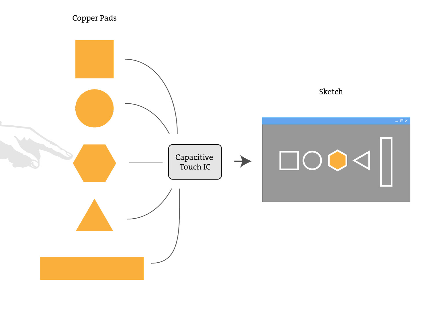
In order to focus on capacitive touch sensing and sound synthesis in this tutorial, I will leave out much of the details behind drawing objects using Processing and instead will provide a ready-to-go code that you will use in the next few steps.
Let’s get started working on the sketch by drawing the shapes on the screen using my “Shape” class and making them respond to the touch.
5.1 Using “Shape” Class
I created a “Shape” class that can draw one of the following five shapes on the screen:
- Hexagon
- Triangle
- Circle
- Square
- Rectangle
This class draws a shape according to the parameters passed into its constructor, for example to draw a square, you would do the following:
Shape square;

void setup() {
  ...
  // Create an instance of the Shape class, specifically, a square
  square = new Shape(x, y, size, rotation, "square");
  ...
}

void draw() {
  // draw the square on the screen
  square.display();
}
The class also implements functionality to make the shapes move back and forth in horizontal direction at a certain frequency when shape.vibrate(frequency) function is used. Here’s an example of creating a hexagon and making it vibrate faster when the mouse is pressed:
Shape hex;

void setup() {
  size(200, 200);
  hex = new Shape(100, 100, 150, 0, "hexagon");
}

void draw() {
  background(100);
  // reset the active state
  hex.setActiveState(false);

  if (mousePressed == true) {
    hex.vibrate(500);
  } else {
    hex.vibrate(200);
  }
  // Draw the shape to the screen
  hex.display();
}
Below is the full listing of the Shape class that we will use to draw shapes on the screen and later we will make them react to touch sensor. Copy it and paste in a new tab within your Processing sketch:
class Shape {
  // This will store the type of shape
  String shapeType;
  // These variables store the initial position of the shape
  float originalXpos;
  float originalYpos;
  // These variables store its current position, rotation and size
  float xpos;
  float ypos;
  float rotation;
  float diameter;
  // Possible deviation from the initial position, in pixels
  int orbitRange = 3;

  // These variables store current time and speed of vibration
  float t = 0.0;
  float speed = 0.5;

  // This variable knows whether the shape is in active state
  boolean active = false;

  Shape(float x, float y, float dia, float rot, String type) {
    originalXpos = x;
    originalYpos = y;
    xpos = x;
    ypos = y;
    shapeType = type;
    diameter = dia;
    rotation = rot;
  }

  // Make the shape "vibrate" in horizontal direction and mark the shape as active
  void vibrate(int frequency) {
    speed = frequency / 1000.0;
    t += speed;
    xpos = originalXpos + orbitRange * cos(t);
    //ypos = originalYpos + orbitRange * cos(t);
    active = true;
  }

  void setActiveState(boolean state) {
    active = state;
  }

  void display() {
    // Draw the shape depending on its type
    switch(shapeType) {
    case "circle":
      pushMatrix();
      translate(xpos, ypos);
      // If the shape is "active", make it appear brighter to highlight it
      if (active) {
        fill(140, 100, 100);
      } else {
        fill(140, 100, 70);
      }
      rectMode(CENTER);
      ellipse(0, 0, diameter, diameter);
      popMatrix();
      break;
    case "square":
      pushMatrix();
      translate(xpos, ypos);
      if (active) {
        fill(280, 100, 100);
      } else {
        fill(280, 100, 70);
      }
      rectMode(CENTER);
      rotate(rotation);
      rect(0, 0, diameter, diameter);
      popMatrix();
      break;
    case "rectangle":
      pushMatrix();
      rectMode(CENTER);
      translate(xpos, ypos);
      if (active) {
        fill(70, 100, 100);
      } else {
        fill(70, 100, 70);
      }
      rotate(rotation);
      rect(0, 0, diameter, diameter*3);
      popMatrix();
      break;
    case "triangle":
      pushMatrix();
      rectMode(CENTER);
      translate(xpos, ypos);
      if (active) {
        fill(200, 100, 100);
      } else {
        fill(200, 100, 70);
      }
      rotate(rotation);
      beginShape();
      for (float a = 0; a < TWO_PI; a += TWO_PI / 3) {
        float sx = cos(a) * diameter/2;
        float sy = sin(a) * diameter/2;
        vertex(sx, sy);
      }
      endShape(CLOSE);
      popMatrix();
      break;
    case "hexagon":
      pushMatrix();
      translate(xpos, ypos);
      rectMode(CENTER);
      if (active) {
        fill(300, 100, 100);
      } else {
        fill(300, 100, 70);
      }
      rotate(rotation);
      beginShape();
      for (float a = 0; a < TWO_PI; a += TWO_PI / 6) {
        float sx = cos(a) * diameter/2;
        float sy = sin(a) * diameter/2;
        vertex(sx, sy);
      }
      endShape(CLOSE);
      popMatrix();
      break;
    default:
      ellipse(xpos, ypos, diameter, diameter);
      break;
    }
  }
}
We can now use this class to draw various shapes and animate their position when touch is detected!
5.2 Using “Shape” class with Touch Sensing
If you recall, when we want to detect whether the touch is detected on one of the 12 electrodes of the MPR121 IC, we do it by checking the result of touch.touched(electrode). Let’s set up the MPR121 IC, create a circle by using the “Shape” class and animate it when the first electrode on the MPR121 IC is touched:
Shape circle;

void setup() {
  size(500, 300);
  // Change the color mode of the sketch to HSB
  colorMode(HSB, 360, 100, 100);
  noStroke();

  // Make a circle of size 100 positioned at some random vertical cordinate
  circle = new Shape(150, random(100, height - 100), 100, 0, "circle");

  touch = new MPR121("i2c-1", 0x5a); // Read capacitive touch from MPR121 using its default address
}

void draw() {
  background(100);

  touch.update(); // get readings from the MPR121 I2C sensor

  // Reset the circle state
  circle.setActiveState(false);

  // If the first electrode is touched, animate the circle position
  if (touch.touched(0)) {
    circle.vibrate(700);
  }

  // Draw the circle
  circle.display();
}
Similarly, we can add the rest of the shapes and connect their state with the state of the electrodes. The code below sets up MPR121 IC, adds all five types of shapes and enables the interaction between the electrodes connected to MPR121 sensor and the shapes on the screen:
import processing.io.*;
MPR121 touch; // define MPR121 I2C capacitive touch sensor

Shape hex;
Shape circle;
Shape triangle;
Shape square;
Shape rectangle;

void setup() {
  size(500, 300);
  // Change the color mode of the sketch to HSB
  colorMode(HSB, 360, 100, 100);
  noStroke();

  hex = new Shape(50, random(100, height - 100), 100, radians(random(360)), "hexagon");
  circle = new Shape(150, random(100, height - 100), 100, radians(random(360)), "circle");
  triangle = new Shape(250, random(100, height - 100), 100, radians(random(360)), "triangle");
  rectangle = new Shape(350, random(100, height - 100), 50, radians(random(360)), "rectangle");
  square = new Shape(450, random(100, height - 100), 100, radians(random(360)), "square");

  touch = new MPR121("i2c-1", 0x5a); // Read capacitive touch from MPR121 using its default address
}

void draw() {
  background(100);

  touch.update(); // get readings from the MPR121 I2C sensor

  // Reset the active state on all shapes
  hex.setActiveState(false);
  circle.setActiveState(false);
  triangle.setActiveState(false);
  square.setActiveState(false);
  rectangle.setActiveState(false);

  // Check every electrode. If it's being touched - animate corresponding shape
  for (int i=0; i < 5; i++) {
    if (touch.touched(i)) {
      if (i == 0) {
        rectangle.vibrate(600);
      }

      if (i == 1) {
        hex.vibrate(440);
      }

      if (i == 2) {
        square.vibrate(490);
      }

      if (i == 3) {
        circle.vibrate(700);
      }

      if (i == 4) {
        triangle.vibrate(340);
      }

    }
  }

  hex.display();
  circle.display();
  triangle.display();
  square.display();
  rectangle.display();
}
With this code ready and the shapes reacting to the touch in a playful way, we can now switch our efforts to sound synthesis.
5.3 Adding Sound Synthesis
In this part of the tutorial, let’s revisit the Sound Library mentioned above. We will use the Sound Library to generate sound via three different types of oscillators: Sine, Square and Triangle oscillators. We will also use the MPR121 sensor in order to turn on or turn off the oscillators. First, let’s use a single oscillator, the sine oscillator, and turn it on when one of the first five electrodes (index of 0-4) is touched. Please take a look at the following code:
import processing.sound.*;
import processing.io.*;
MPR121 touch; // define MPR121 I2C capacitive touch sensor

// Create 5 Sine wave oscillators (1 for each electrode that acts as a separate key)
SinOsc sinOsc[] = new SinOsc[5];

void setup() {
  size(500, 300);

  // Read capacitive touch from MPR121 using its default address
  touch = new MPR121("i2c-1", 0x5a);

  // initialize arrays of oscillators
  for (int i=0; i < 5; i++) {
    sinOsc[i] = new SinOsc(this);
  }
}

void draw() {
  background(100);

  touch.update(); // get readings from the MPR121 I2C sensor

  for (int i=0; i < 5; i++) {
    // If the electrode is not touched, stop the oscillator
    if (!touch.touched(i)) {
      sinOsc[i].stop();
    }
    if (touch.touched(i)) {
      if (i == 0) {
        sinOsc[i].play(600, 1.0);
      }

      if (i == 1) {
        sinOsc[i].play(440, 1.0);
      }

      if (i == 2) {
        sinOsc[i].play(490, 1.0);
      }

      if (i == 3) {
        sinOsc[i].play(700, 1.0);
      }

      if (i == 4) {
        sinOsc[i].play(340, 1.0);
      }

    }
  }

}
Now let’s expand this to the other 2 types of oscillators, the square and the triangle oscillators. Let’s also move the oscillators’ play and stop operations into separate functions:
import processing.sound.*;
import processing.io.*;
MPR121 touch; // define MPR121 I2C capacitive touch sensor

// Create 5 instances of each type of oscillators (1 for each electrode that acts as a separate key)
SinOsc sinOsc[] = new SinOsc[5];
SqrOsc sqrOsc[] = new SqrOsc[5];
TriOsc triOsc[] = new TriOsc[5];

// This is used for switching between oscillators: 0 - Sine, 1 - Square, 2 - Triangle oscillator
int currentMode;

void setup() {
  size(500, 300);

  // Read capacitive touch from MPR121 using its default address
  touch = new MPR121("i2c-1", 0x5a);

  // initialize arrays of oscillators
  for (int i=0; i < 5; i++) {
    sinOsc[i] = new SinOsc(this);
    sqrOsc[i] = new SqrOsc(this);
    triOsc[i] = new TriOsc(this);
  }

  currentMode = 0; // set the default oscillator to Sine
  //currentMode = 1; // uncomment this to set the default oscillator to Square
  //currentMode = 2; // uncomment this to set the default oscillator to Triangle
}

void draw() {
  background(100);

  touch.update(); // get readings from the MPR121 I2C sensor

  for (int i=0; i < 5; i++) {
    // If the electrode is not touched, stop the oscillator
    if (!touch.touched(i)) {
      stopNote(i);
    }
    if (touch.touched(i)) {
      if (i == 0) {
        playNote(i, 600);
      }

      if (i == 1) {
        playNote(i, 440);
      }

      if (i == 2) {
        playNote(i, 490);
      }

      if (i == 3) {
        playNote(i, 700);
      }

      if (i == 4) {
        playNote(i, 340);
      }

    }
  }

}

// Play a note, using the oscillator that is currently active
void playNote(int index, int frequency) {
  switch(currentMode) {
  case 0:
    sinOsc[index].play(frequency, 1.0);
    break;
  case 1:
    sqrOsc[index].play(frequency, 1.0);
    break;
  case 2:
    triOsc[index].play(frequency, 1.0);
    break;
  }
}

// Stop playing the note
void stopNote(int index) {
  sinOsc[index].stop();
  sqrOsc[index].stop();
  triOsc[index].stop();
}
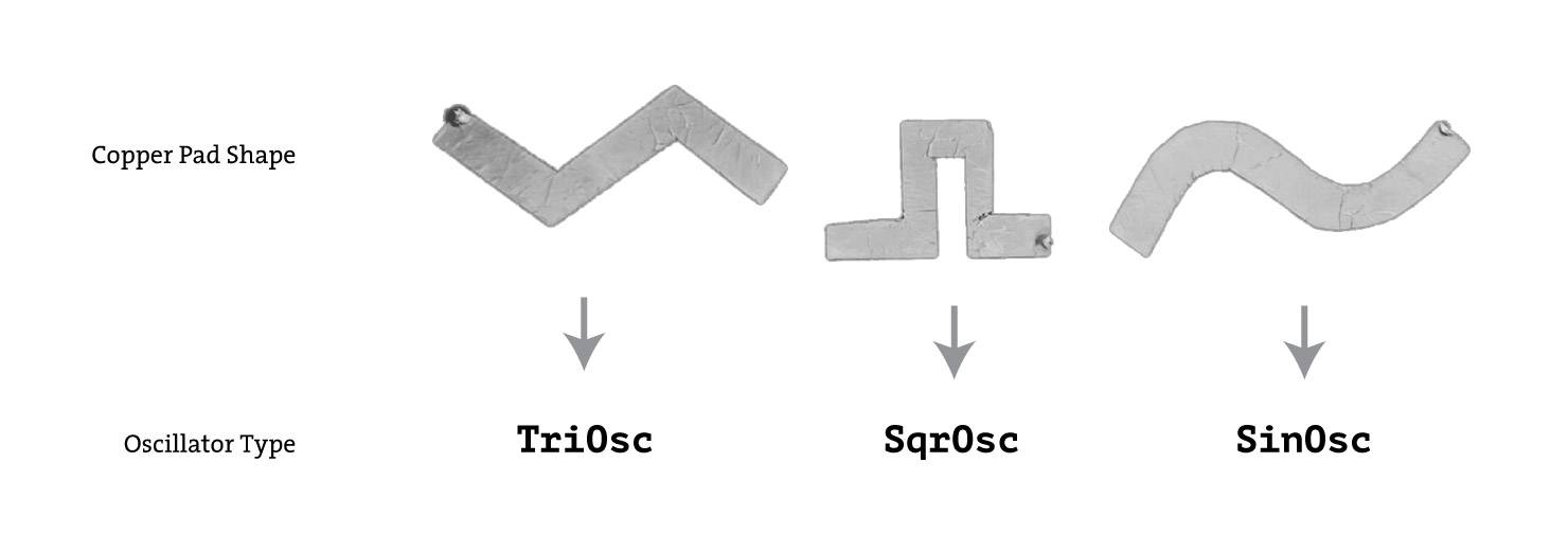
Currently, in order to switch between different types of oscillators, you would need to change the value of the currentMode variable. Let’s make this easier by using three capacitive touch pads that will correspond to each oscillator type. I cut out the following three shapes out of copper tape and later we can connect them in code to each of the oscillator types:
In code, it would look something like this:
...
int currentMode; // Used for switching between oscillators: 0 - Sine, 1 - Square, 2 - Triangle oscillator
...
void setup() {
  ...
  currentMode = 0;
  ...
}

void draw() {
  ...
  // Pin 8 is connected to Sine wave shape
  if (touch.touched(8)) {
    currentMode = 0;
  }

  // Pin 5 is connected to Square wave shape
  if (touch.touched(5)) {
    currentMode = 1;
  }

  // Pin 6 is connected to Triangle wave shape
  if (touch.touched(6)) {
    currentMode = 2;
  }
  ...
}
With the ability to switch between the three types of oscillators, we can now add sound modifiers such as volume and pitch.
5.4 Adding Sound Modifiers
In this section, we will use the methods previously discussed, analogRead and touch.touched(i) to add volume and pitch modifiers. The addition of analogRead will make our modifiers more dynamic and more interesting.
Volume Modifiers
Let’s add a couple pads that will change the volume of the sound. Touching the first one will simply toggle between three levels of volume, and touching another one will make the volume proportional to analogRead() value of that pad. Here is the sketch code that adds the two volume modifiers that are attached to pin 10 and pin 7:
...
float[] volumeLevels = {0.5, 0.75, 1.0}; // possible volume levels to switch between
int currentVolumeIndex = 0;
float currentVolume = 1.0;
...
void setup(){
  ...
  currentVolume = volumeLevels[currentVolumeIndex]; // set the current volume to 0.5
  ...
}

void draw(){
  ...
  if (touch.touched(10)) {
    // increase index of the volume slider
    currentVolumeIndex++;
    if (currentVolumeIndex > volumeLevels.length - 1) {
      currentVolumeIndex = 0;
    }
    currentVolume = volumeLevels[currentVolumeIndex]; //switch volume to the next volume level
  }

  // if pin 7 is not touched, just use the last known volume
  if (!touch.touched(7)) {
    currentVolume = volumeLevels[currentVolumeIndex];
  }

  // if pin 7 is touched, set the current volume to be proportional to analogRead value
  if (touch.touched(7)) {
    currentVolume = touch.analogRead(7) / 200.0;
  }
  ...
}

// To use the currentVolume variable, we will do it in .play method of the oscillators:
sinOsc[index].play(frequency, currentVolume);
Pitch Modifier
Similarly to the volume modifier, we can add a pitch modifier! The pitch modifier will serve the function similar to a the pitch wheel on a regular synthesizer, just slightly changing the frequencies of the sounds. With the use of analogRead() it is possible to achieve similar (though less predictable) feature in our capacitive touch musical instrument.
Let’s review the code that we used to play simple notes:
...
playNote(i, 440);
...
void playNote(int index, int frequency) {
  switch(currentMode) {
  case 0:
    sinOsc[index].play(frequency, 1.0);
    break;
  case 1:
    sqrOsc[index].play(frequency, 1.0);
    break;
  case 2:
    triOsc[index].play(frequency, 1.0);
    break;
  }
}
Let’s work a bit on that frequency part. We can add two conductive pads that behave similar to the volume modifiers, one will toggle between frequency level, and another one will just slightly affect the volume level. We can incorporate both of those pads affecting the frequency variable as follows:
frequencyMultiplier = value of the toggle;
pitchDelta = value of the analogRead on some pin
...
sinOsc[index].play(frequency * frequencyMultiplier + pitchDelta, 1.0);
...
And here’s the code that fully implements this idea of the pitch wheel:
float pitchDelta = 0;
float frequencyMultiplier = 1.0;

void draw(){
  ...
  // When pin 9 is not touched, don't modify the pitch
  if (!touch.touched(9)) {
    pitchDelta = 0;
  }

  // When pin 9 is touched, modify the pitch in proportion to analogRead() value
  if (touch.touched(9)) {
    pitchDelta = touch.analogRead(9) / 2;
  }

  // Don't modify frequency multiplier if pin 11 is not touched
  if (!touch.touched(11)) {
    frequencyMultiplier = 1.0;
  }

  // Increase frequency multiplier when pin 11 is touched
  if (touch.touched(11)) {
    frequencyMultiplier = 3.0; // Feel free to change this value
  }
  ...
}

void playNote(int index, int frequency) {
  switch(currentMode) {
  case 0:
    sinOsc[index].play(frequency * frequencyMultiplier + pitchDelta, currentVolume);
    break;
  case 1:
    sqrOsc[index].play(frequency * frequencyMultiplier + pitchDelta, currentVolume);
    break;
  case 2:
    triOsc[index].play(frequency * frequencyMultiplier + pitchDelta, currentVolume);
    break;
  }
}
With the volume and pitch modifier added to the sketch, we can now put all the parts together!
5.4 Connecting all parts together
So far we were able to do the following:
- Animate shapes in response to touch
- Produce sound when pins are touched
- Modify the volume and pitch of the sound
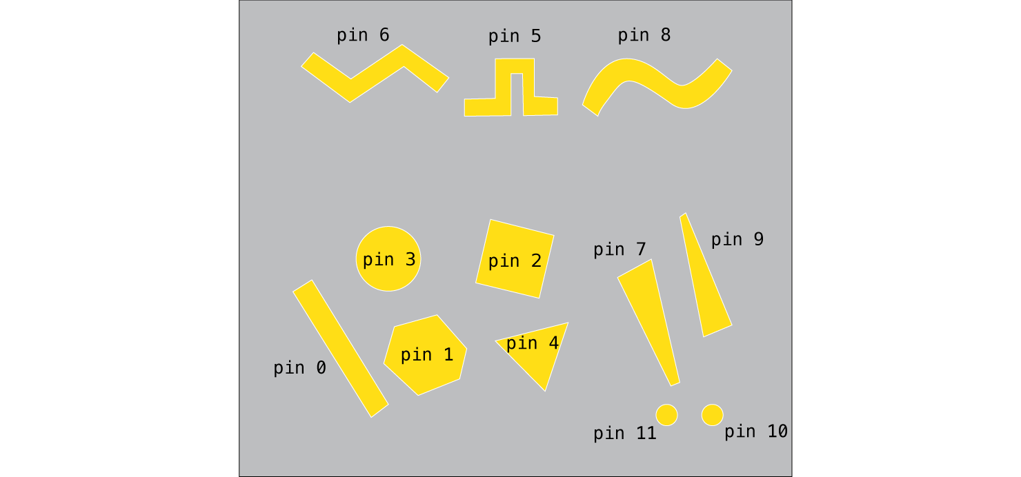
Now let’s wrap everything up and put together all the bits and pieces into a single sketch. I created a diagram of the board layout and pin mapping:
And finally, the complete Processing sketch is as follows:
import processing.sound.*;
import processing.io.*;
MPR121 touch; // define MPR121 I2C capacitive touch sensor

Shape hex;
Shape circle;
Shape triangle;
Shape square;
Shape rectangle;

SinOsc sinOsc[] = new SinOsc[5];
SqrOsc sqrOsc[] = new SqrOsc[5];
TriOsc triOsc[] = new TriOsc[5];

float[] volumeLevels = {0.5, 0.75, 1.0}; // possible volume levels to switch between
int currentVolumeIndex = 0;
float currentVolume = 1.0;

float pitchDelta = 0;
float frequencyMultiplier = 1.0;

int currentMode; // Used for switching between oscillators: 0 - Sine, 1 - Square, 2 - Triangle oscillator

void setup() {
  size(500, 300);
  // Change the color mode of the sketch to HSB
  colorMode(HSB, 360, 100, 100);
  noStroke();

  hex = new Shape(50, random(100, height - 100), 100, radians(random(360), "hexagon");
  circle = new Shape(150, random(100, height - 100), 100, radians(random(360), "circle");
  triangle = new Shape(250, random(100, height - 100), 100, radians(random(360), "triangle");
  rectangle = new Shape(350, random(100, height - 100), 50, radians(random(360), "rectangle");
  square = new Shape(450, random(100, height - 100), 100, radians(random(360), "square");

  touch = new MPR121("i2c-1", 0x5a); // Read capacitive touch from MPR121 using its default address
  for (int i=0; i < 5; i++) {
    sinOsc[i] = new SinOsc(this);
    sqrOsc[i] = new SqrOsc(this);
    triOsc[i] = new TriOsc(this);
  }

  currentVolume = volumeLevels[currentVolumeIndex];
  currentMode = 0; // set the default oscillator to Sine
}

void draw() {
  background(100);

  touch.update(); // get readings from the MPR121 I2C sensor

  hex.setActiveState(false);
  circle.setActiveState(false);
  triangle.setActiveState(false);
  square.setActiveState(false);
  rectangle.setActiveState(false);

  if (touch.touched(10)) {
    currentVolumeIndex++;
    if (currentVolumeIndex > volumeLevels.length - 1) {
      currentVolumeIndex = 0;
    }
    currentVolume = volumeLevels[currentVolumeIndex];
  }

  if (!touch.touched(9)) {
    pitchDelta = 0;
  }

  if (touch.touched(9)) {
    pitchDelta = touch.analogRead(9) / 2;
  }

  if (!touch.touched(7)) {
    currentVolume = volumeLevels[currentVolumeIndex];
  }

  if (touch.touched(7)) {
    currentVolume = touch.analogRead(7) / 200.0;
  }

  if (!touch.touched(11)) {
    frequencyMultiplier = 1.0;
  }

  if (touch.touched(11)) {
    frequencyMultiplier = 3.0;
  }

  if (touch.touched(8)) {
    currentMode = 0;
  }

  if (touch.touched(5)) {
    currentMode = 1;
  }

  if (touch.touched(6)) {
    currentMode = 2;
  }

  for (int i=0; i < 5; i++) {
    if (!touch.touched(i)) {
      stopNote(i);
    }
    if (touch.touched(i)) {
      if (i == 1) {
        hex.vibrate(440);
        playNote(i, 440);
      }

      if (i == 3) {
        // Update the circle state
        circle.vibrate(700);
        playNote(i, 700);
      }

      if (i == 4) {
        triangle.vibrate(340);
        playNote(i, 340);
      }

      if (i == 2) {
        square.vibrate(490);
        playNote(i, 490);
      }

      if (i == 0) {
        rectangle.vibrate(600);
        playNote(i, 600);
      }
    }
  }

  hex.display();
  circle.display();
  triangle.display();
  square.display();
  rectangle.display();
}

// Play a note, using the oscillator that is currently active, with volume level established by the volume toggle switch
void playNote(int index, int frequency) {
  switch(currentMode) {
  case 0:
    sinOsc[index].play(frequency * frequencyMultiplier + pitchDelta, currentVolume);
    break;
  case 1:
    sqrOsc[index].play(frequency * frequencyMultiplier + pitchDelta, currentVolume);
    break;
  case 2:
    triOsc[index].play(frequency * frequencyMultiplier + pitchDelta, currentVolume);
    break;
  }
}

void stopNote(int index) {
  sinOsc[index].stop();
  sqrOsc[index].stop();
  triOsc[index].stop();
}
I hope your musical instrument is working after this long journey! Of course I’d encourage you to play with the different values for note frequencies, pitch, volume and experiment with the conductive materials and not limit yourself. There’s plenty of room to personalize the result and make it even more interesting to interact with.
Next Steps
Some of the next steps you could take from here are:
- Make a box for your musical instrument.
- Connect buttons and knobs in addition to capacitive touch pads. You can refer to another tutorial on this site on how to connect buttons. For knobs (potentiometers), you would need an Analog-to-Digital converter connected to SPI or I2C bus.
- Experiment with other conductive materials listed in “What to use for the electrodes” section.